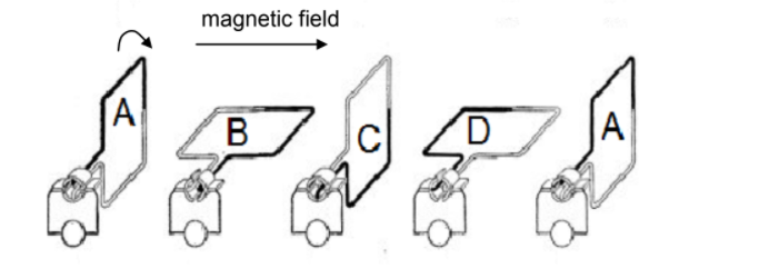
10.1 The diagram below shows different positions (ABCDA) of the coil in a DC generator for a complete revolution. The coil is rotated clockwise at a constant speed in a uniform magnetic field.
The direction of the magnetic field is shown in the diagram below.
10.1.1 Write down the energy conversion that takes place during the operation of the DC generator. (1)
10.1.2 Sketch a graph to show how the induced emf of the generator varies with time. Clearly indicate positions A, B, C, D and A on the graph. (2)
10.2 A small AC generator, providing an rms voltage of 25 V, is connected across a device with a resistance of 20 Ω. The wires connecting the generator to the device have a total resistance of 0,5 Ω. Refer to the diagram below.

10.2.1 Write down the total resistance of the circuit. (1)
10.2.2 Calculate the average power delivered to the device. (5)
[9]