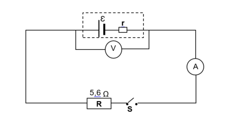
In the circuit diagram below, resistor R,with a resistance of 5,6 Ω, is connected, together with a switch, an ammeter and a high-resistance voltmeter, to a battery with an unknown internal resistance, r.
The resistance of the connecting wires and the ammeter may be ignored.
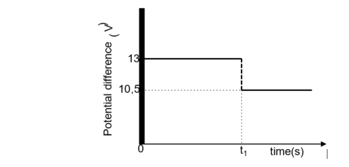
The graph below shows the potential difference across the terminals of the battery as a function of time.
At time t1, switch S is closed.
8.1 Define the term emf of a battery. (2)
8.2 Write down the value of the emf of the battery. (1)
8.3 When switch S is CLOSED, calculate the:
8.3.1 Current through resistor R (3)
8.3.2 Power dissipated in resistor R (3)
8.3.3 Internal resistance, r, of the battery (3)
8.4 Two IDENTICAL resistors, each with resistance X, are now connected in the same circuit with switch S
closed, as shown below.
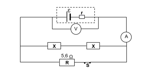
The ammeter reading now increases to 4 A.
8.4.1 How would the voltmeter reading change? Choose from INCREASES, DECREASES or REMAINS THE SAME.
Give a reason for the answer by referring to Vinternal resistance. (2)
8.4.2 Calculate the resistance x (5)
[19]